For the following calculations we will only consider plates of uniform thickness and with a uniformly distributed load over the entire surface.
This will help us define minimum thickness’ for components such as pressure vessels or piston housings.
For the purpose of sizing calculations we can assume that for a bolted junction a simply supported equation is appropriate. For integrated end cap geometry, we can assume the fixed supported equation.
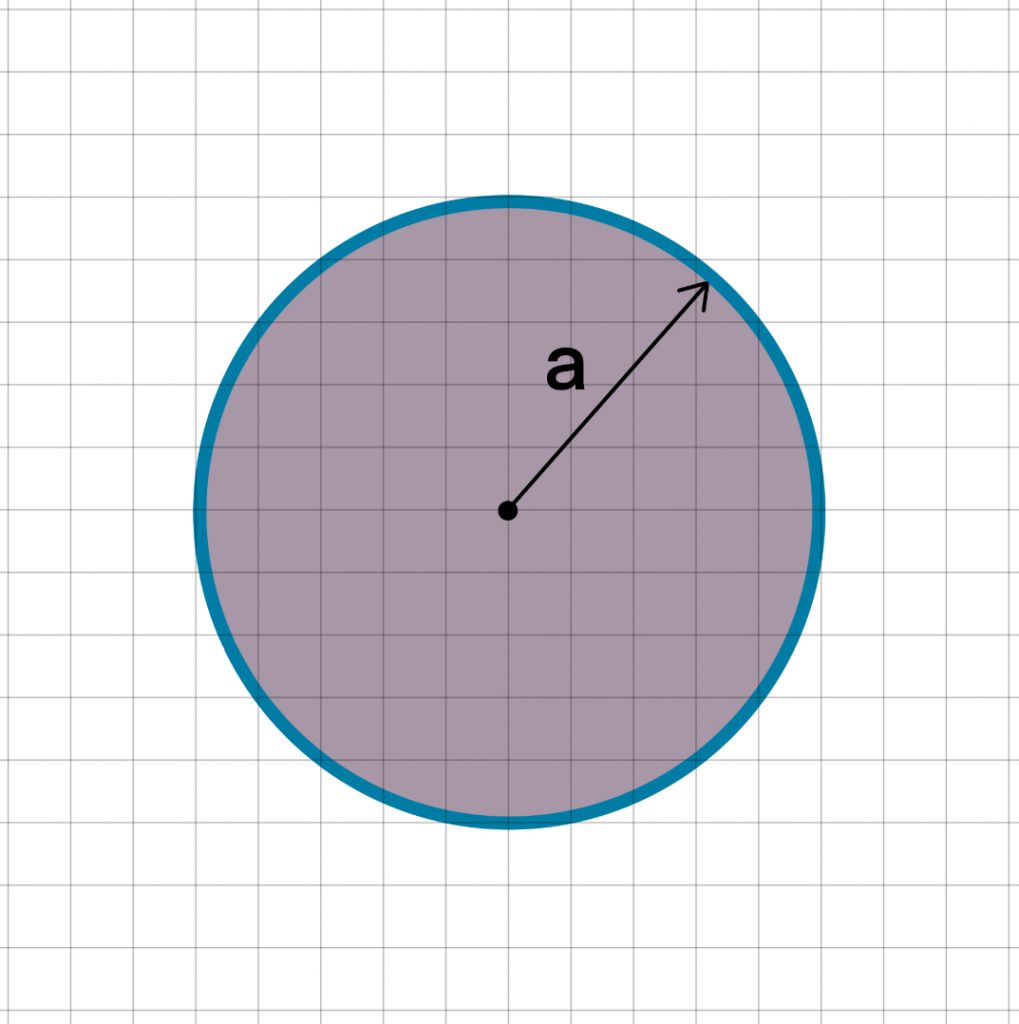
Simply Supported
The maximum bending stress (at the centre) of a simply supported plate can be calculated by:
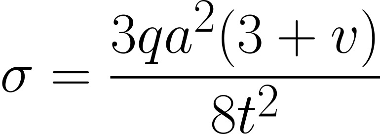
Typically values of v for metallic plates is 0.3
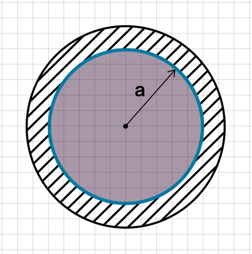
Fixed Supported
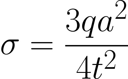
For a plate that is fixed supported i.e. built into the structure, the maximum bending stress (at the supported edge) can be calculated by:
For pressurised components, it is common to see that end caps are domed in shape.
The purpose of this is to remove the internal right angle geometry, which can lead to a high risk of failure. The smoothed dome geometry helps to remove this stress concentration.
Having a continuously smooth loop, the pressure vectors smoothly transition around the perimeter – no prying mechanism involved – only hoop stress, which are much more easily managed.
For more information on hoop stresses, check out our post on cylinders stresses here
Leave a Reply
You must be logged in to post a comment.