A detailed guide to spur gear design covering teeth count, module, pressure angle, and face depth. Includes formulas and real-world considerations for engineers.

Spur gears are fundamental components in mechanical power transmission systems, serving as the backbone for countless applications from precision instruments to heavy industrial machinery. Their design requires careful consideration of multiple parameters to achieve optimal performance, reliability, and cost-effectiveness.
This comprehensive guide explores the critical design parameters of spur gears, providing you with essential knowledge to make informed decisions. We’ll examine how each parameter affects gear performance and discuss the trade-offs involved in their selection.
Whether you’re designing a small precision mechanism or a heavy-duty power transmission system, these principles will help guide your decision-making process.
Number of Teeth
The number of teeth on a spur gear significantly impacts several performance characteristics:
- Contact ratio: More teeth generally results in a higher contact ratio, leading to smoother operation and reduced noise
- Load distribution: Higher tooth counts distribute the load across more teeth simultaneously, potentially reducing wear on individual teeth
- Angular velocity fluctuation: More teeth result in less variation in angular velocity during mesh, providing more consistent motion
- Gear size: For a given module, more teeth result in a larger gear diameter, which may impact space constraints
- Manufacturing complexity: Higher tooth counts can be more challenging to manufacture accurately, potentially increasing costs
Too few teeth can result in interference and undercutting issues, too many teeth may lead to teeth that are too small to manufacture reliably or carry the required load
Preferred number of teeth per gear are:
12, 13, 14, 15, 16, 18, 20, 22, 24, 25, 28, 30, 32, 34, 38, 40, 45, 50, 54, 60, 64, 70, 72, 75, 80, 84, 90, 96, 100, 120, 140, 150, 180, 200, 220, 250
Module
The module (m) is a fundamental parameter in gear design that defines the physical size of the gear teeth. The module controls the relationship between the gear (reference) diameter and the number of teeth. In general the larger the module, the stronger the teeth but fewer teeth for a given diameter.
The selection of module depends on several factors:
- Required gear strength and load capacity
- Space constraints
- Manufacturing capabilities
- Cost considerations
- Required precision and smoothness of operation
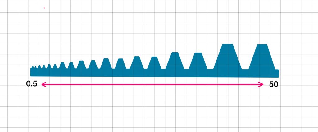
Preferred values of gear module are:
0.5, 0.8, 1, 1.25, 1.5, 2.5, 3, 4, 5, 6, 8, 10, 12, 16, 20, 25, 32, 40
Pressure Angle
The pressure angle of a gear tooth is a key variable in spur gear design, however, 20 degrees has become the industry standard for most general-purpose gearing applications. A 20-degree pressure angle represents an optimal balance between these factors for most applications. It provides:
- Good load carrying capacity
- Reasonable tooth strength
- Acceptable contact ratio
- Moderate sliding velocities
Higher pressure angles in spur gears cause:
- Increased tooth strength at the base due to thicker tooth profile
- Better load distribution and higher load carrying capacity
- Reduced likelihood of interference between mating teeth
- Higher contact stress between teeth
- Increased radial forces on bearings
- Generally higher operating noise levels
Therefore, high pressure angles (25° or 30°) are typically used in heavy-duty applications where strength and load capacity are prioritized over noise and smooth operation.
Lower pressure angles (14.5°) in spur gears result in:
- Thinner tooth profiles, leading to reduced tooth strength
- Better contact ratio between mating teeth
- Smoother and quieter operation
- Lower radial forces on bearings
- Increased risk of interference between mating teeth
- Reduced load carrying capacity
Low pressure angles are typically used in applications where smooth, quiet operation is prioritized over high load capacity, such as precision instruments and low-power applications.
Face Depth
Face depth (also known as face width) is a critical dimension that affects several aspects of spur gear performance:
- Load capacity: Wider face width increases the contact area between mating gears, allowing for higher load transmission
- Heat dissipation: Greater face width provides more surface area for heat dissipation during operation
- Wear distribution: Adequate face width helps distribute wear more evenly across the gear teeth
- Alignment sensitivity: Wider faces can be more sensitive to misalignment issues between shafts
- Manufacturing cost: Larger face widths require more material and machining time, increasing production costs
A good starting value for a gear face depth should be 9 to 16 x module, or in a rack and pinion configuration the rack gear face should be up to 60% of the pinion diameter. This value must be validated through strength and durability calculations!
Gear Relationship
The following equations outline the basic dimensions for sizing a spur gear.

Note, it is acceptable to modify these values, however, any changes will affect gear performance in both good and bad ways!
| Number of Teeth | z | ||
| Module | m | mm | |
| Pressure Angle | a | 20 | deg |
| Pitch Circle Diameter | d | z m | mm |
| Outside Diameter | Do | d + 2m | mm |
| Inner Diameter | Di | d – 2.5m | mm |
| Tooth Height | h | 2.5m | mm |
| Addendum | ha | m | mm |
| Dedendum | hf | 1.25m | mm |
| Tooth Pitch | p | m*pi | mm |
| Tooth Thickness | ctt | p/2 | mm |
| Root Fillet | rf | 0.38m | mm |
| Top Land Width (min) | to | 0.25m | mm |
Relationship between gears
| Ratio | zpinion / zgear | ||
| Center Distance | a | (dpinion + dgear) /2 | mm |
ELEVATE YOUR KNOWLEDGE
Check out the links to see:
- Example Calculations
See how these equations turn into solutions - CAD and Drawing Examples
How to draw and instruct gear geometry on a 2D technical drawing
Leave a Reply
You must be logged in to post a comment.