In How to Calculate Lug Stresses we spoke about lugs being a great way to transmit mechanical load when used with a clevis pin.
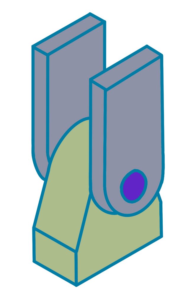
The following equations will allow us to size the correct size pin for this application.
Pin Bending Stress
As a conservative approach, the load on the pin can be assumed as uniformly distributed across its length for bending purposes.
A weak pin can cause premature failure of the lug by imparting excessive strains at the shear faces
The following approach will ensure that the pin is sufficiently stiff in order to counteract this type of failure.
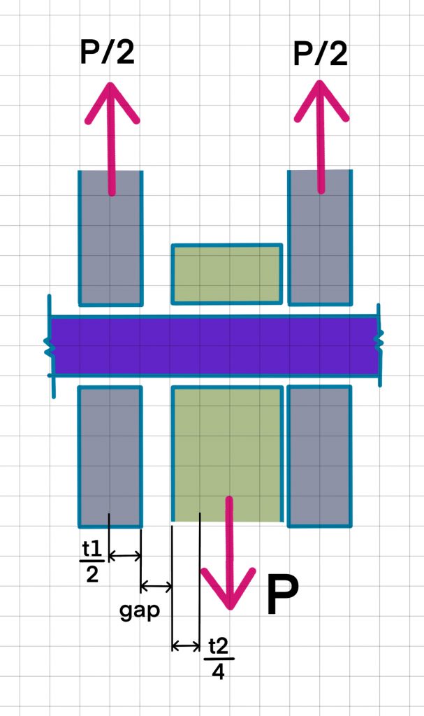
Bending Moment in Pin
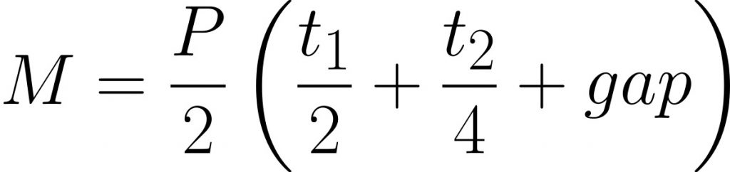
t2=Thickness of inner lug/plate, gap = gap between outer and inner lug
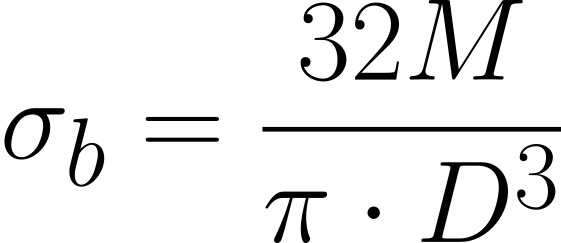
Bending Stress in Pin
You can see that when calculating the bending moment in the pin, the gap between the lugs is hugely influential in the amount of bending stress seen in the pin. Minimising these gaps can help reduce bending loads and therefore component sizes!
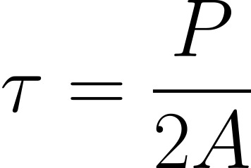
Pin Shear Stress
To calculate the shear stress in the pin, we can take the applied load P and divided that by the pin cross sectional area. Note that the applied load P is shared across both outer lugs/plates, therefore can be divided by 2!
Leave a Reply
You must be logged in to post a comment.