Essentially, a lug is just a plate with a hole in it! But when used with a clevis pin lugs are a useful way to transmit mechanical load through mechanical components with quick and easy installation.
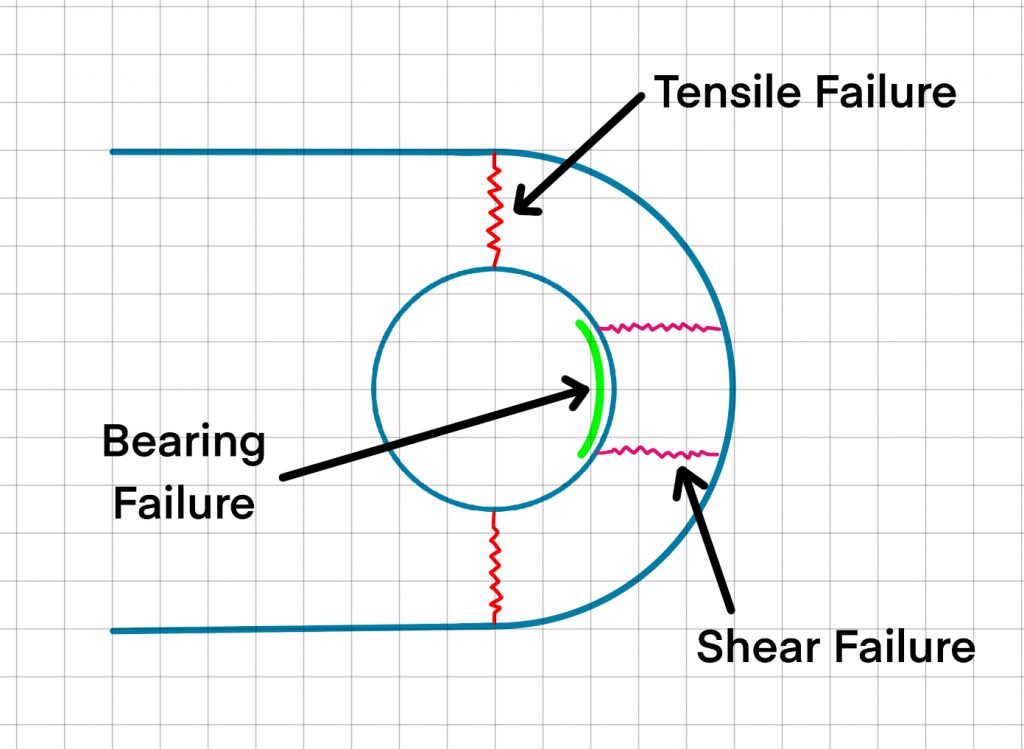
There are several failure modes to consider when it comes to sizing a lug. The following simplified method will consider the following:
- Tension Failure
- Shear Failure
- Bearing Failure

Axial Loading
Tensile Stress in lug:
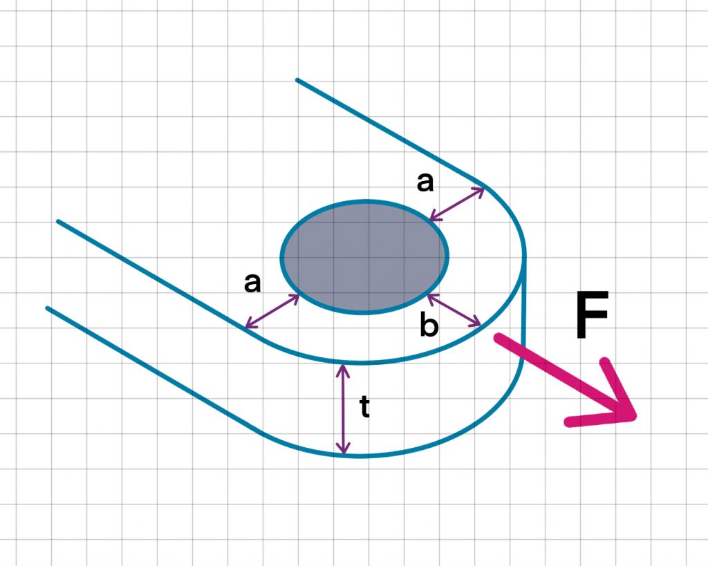
Tensile failure of a lug in axial loading will occur perpendicular to the applied load at the position of minimum cross section.
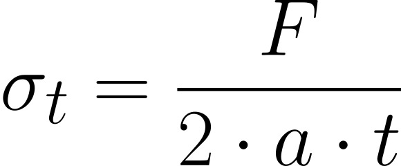
Tapering the lug profile will increase the minimum cross section ‘a’
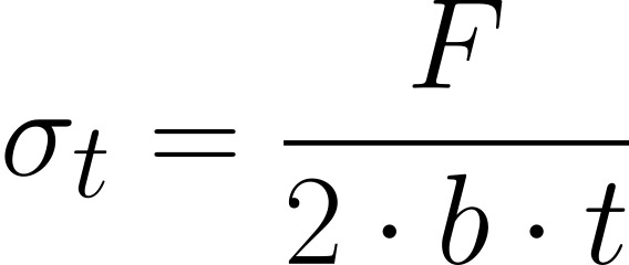
Shear Stress in lug:
Shear failure will typically occur across two planes, it can be common practice to consider a 40 degree line extending from the centre of the pin to the lug hole and project the shear failure out horizontally. A more simple and conservative approach is to calculate and apply the length ‘b’.
Bearing Load:
A bearing load will occur between the pin and the lug hole surfaces. Bearing failure will occur in the component with the minimum ultimate bearing strength. If a bushing or bearing or is used between the pin and lug hole surface, then bearing load must be calculated at both interfaces i.e. pin to bushing and bushing to lug.
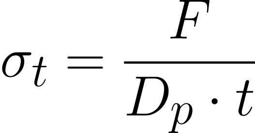
The bearing strength of a material can be approximated as x1.5 ultimate tensile strength
Leave a Reply
You must be logged in to post a comment.