GD&T
Geometric Dimensioning and
Tolerancing
Geometric dimensions and tolerances (GD&T) allows you, the designer, to control the dimension, fit and form of a part in way that reflects the intended function of the part and/or assembly. These instructions, typically detailed with symbols on a 2D drawing, allow you to communicate which areas of the design are of the highest importance.
These geometric characteristics are assigned to features or surfaces using feature control frames. These frames communicate all the information required to fully control the size, shape, and location of the respective feature.
GD&T symbols are neatly grouped according to their function.
Dimensions and Datums
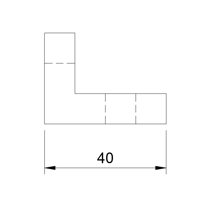
Linear Dimensions
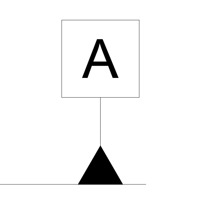
Datums
Datum Reference Frames
Coming Soon…
How to Establish a Datum Systems in 2D Technical Drawings
Coming Soon…
Datum Targets
Coming Soon…
Form Features
Form features make for a great foundation for any 2D technical drawing. When starting to dimension and tolerance a component, always think ‘Form Features First’. Although they cannot control the size or orientation of a feature, instead they are used when we wish to control the variation or ‘waviness’ of a feature. For example form features are critical when we wish to control sealing features or provide an even amount of wear between mating parts.
Straightness
Flatness
Roundness
Cylindricity
Orientation
Orientation can be defined in two ways. Most commonly they are applied to control the deviation in a planar surface with respect to a surface datum. In this instance, the tolerance zone is bounded by two parallel planes.
Alternatively, parallelism, perpendicularity and angularity can be applied to a hole or cylindrical axis, where the tolerance zone is defined as a 3D cylindrical tolerance zone defined by a line feature relative to a planar or axial datum.
Orientation features can be controlled using basic or theoretically exact dimensions (TED) which are denoted as a boxed dimension on the drawing. TED’s refer to the theoretically perfect position of the defined feature, therefore, they have no tolerance associated to them. More importantly, they must relate back to the respective datum called out in the control frame.
Parallelism
Perpendicularity
Angularity
Location
Although linear dimensions can be used successfully dimension feature on a 2D technical drawing, location control features can elevate your intentions to a whole new level.
Location control features have the following advantages compared with linear dimensions:
- There is no accumulation of tolerances. Location control features can be located with theoretical exact dimensions (TEDs) allowing for a more simple tolerance calculations.
- Functional relationships to one or more datums are directly indicated
- Allows you to indicate cylindrical tolerance zones. This can reduce positional error by 39%
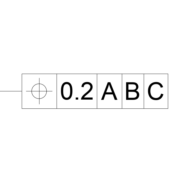
Position
Concentricity
Symmetry
Profile
Profile tolerances are can be applied in two ways; a line or a surface profile. Both are usually applied to irregular shapes where other tolerances are difficult communicate or cannot be used.
A line profile will typically apply to a specified cross section(s) in a component at which the boundary is controlled by a 2D tolerance zone with relation to the nominal boundary.
Unlike a line profile tolerance, a surface profile tolerance is applied to the whole feature and is controlled by a 3D tolerance zone typically bound by two offset surfaces to the nominal.
Line Profile
Surface Profile
Run-Out
A more specialist geometric tolerance, run-out tolerances combine a number of other geometric features including; co-axiality, roundness, cylindricality and even perpendicularity and flatness into a specialist type of geometric tolerances specifically for rotary parts.
Both circular and total run-out are applied to a component to control its circular or cylindrical features as the component is rotated through 360 degrees.